 Verdant stock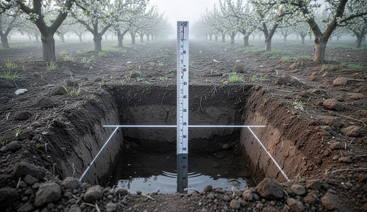

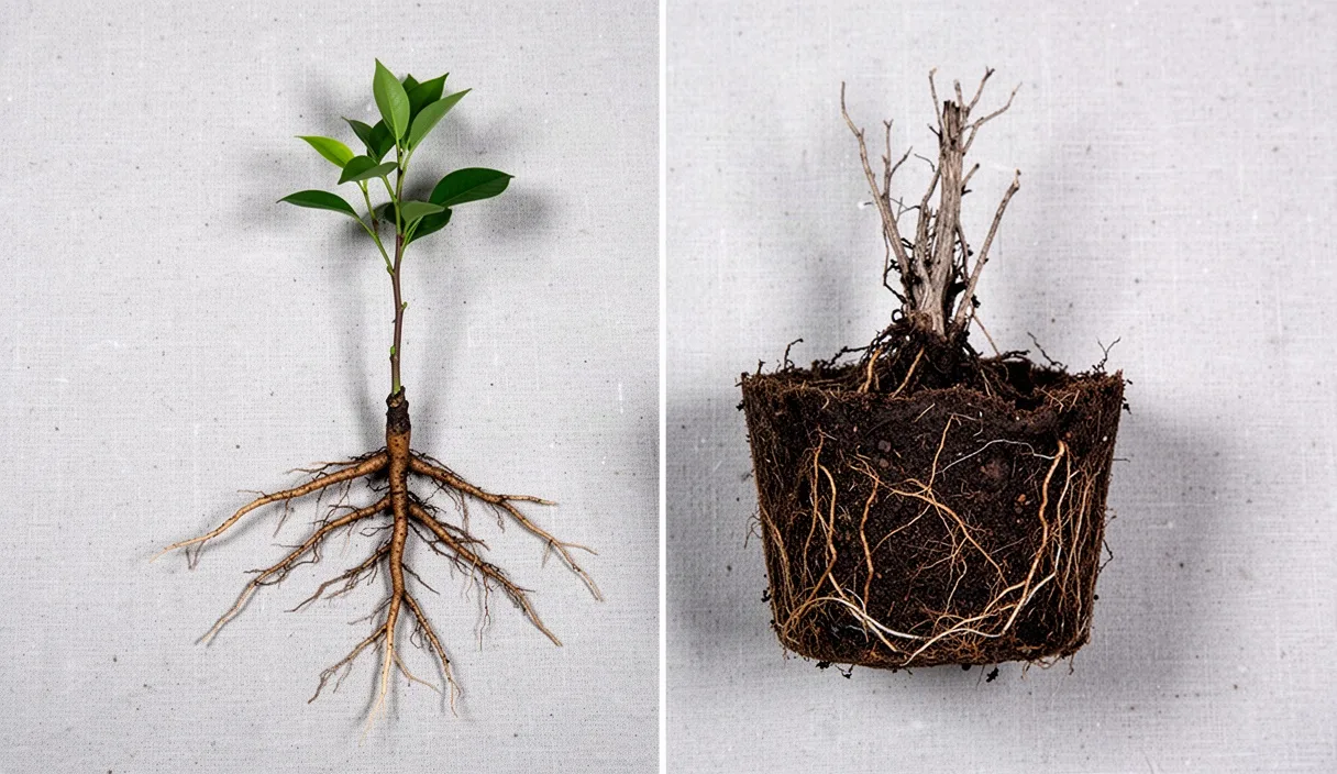
Establishing an orchard represents a multi-decade capital commitment where mistakes made during site evaluation compound across every growing season. Tree roots require an equilibrium between available moisture and gaseous exchange within the soil matrix. When internal drainage is restricted, gravitational water displaces air from macropores, creating anaerobic conditions that halt cellular respiration in root tips. Within 48 hours of prolonged saturation, susceptible root tissues suffer cellular collapse, opening pathways for soil-borne pathogens such as Phytophthora cactorum and Pythium species to colonize the root system.
Surface infiltration, which measures the rate at which water enters the topsoil horizon, does not provide an accurate assessment of subsoil drainage. A site may display rapid topsoil water acceptance while concealing a dense structural layer 45 centimeters below grade that holds a perched water table. Quantifying subsoil saturated hydraulic conductivity through standardized field percolation procedures provides the physical data necessary to determine row orientation, rootstock selection, planting bed architecture, or the mechanical installation of subsurface tile infrastructure.
Dimensions for Test Holes Across Nursery Blocks
Accurate field percolation data requires test bore dimensions that intersect the actual rooting zone of the intended tree crop. For standardized deciduous fruit and nut rootstocks, such as semi-dwarfing apple selections or deep-rooting stone fruit stocks, hole depth must match the primary active root volume, which sits between 60 and 90 centimeters below native grade. In shallow-rooted berry blocks, a 45-centimeter depth is sufficient, whereas walnut or pecan blocks require excavation to 100 centimeters to evaluate the prospective taproot corridor.
The borehole diameter should remain uniform between 15 and 20 centimeters. Using a diameter narrower than 15 centimeters restricts the field gauge placement and risks excessive wall sloughing during measurement. Diameters wider than 25 centimeters require excessive water volumes during the pre-soak phase without improving the precision of the hydraulic calculation. Holes should be excavated using a hand auger with sharp cutting edges or an excavator mounted with an earth auger operated at low rotational speeds.
Mechanical drilling often causes mechanical compaction and clay smearing along the cylindrical perimeter of the borehole. Smeared sidewalls seal soil macropores, creating an artificial barrier that yields false-negative drainage readings. The excavator or field technician must prepare the interior surfaces prior to testing using the following procedure:
- Scrape the interior sidewalls vertically using a stiff wire brush or the serrated edge of a soil knife to expose the natural ped structure and reopen sheared pores.
- Clear all loose crumb and fallen aggregates from the flat base of the hole using a vacuum tube, hand scoop, or cup auger.
- Deposit 5 centimeters of washed pea gravel (particle sizing between 6 and 10 millimeters) directly at the bottom of the excavation. This gravel layer prevents water scouring, inhibits sediment suspension when refilling, and establishes a stable reference floor for measuring instruments.
Testing frequency depends on topsoil heterogeneity and the topographical relief of the parcel. For uniform valley floors with consistent soil series mappings, conduct one test hole per 0.8 hectares. On rolling ground, alluvial fans, or terrain marked by cut-and-fill historical grading, establish a grid spacing of one test hole per 0.3 hectares. Ensure that low swales, slope transitions, and high knolls contain dedicated test stations, as internal soil drainage can vary significantly across a single 30-meter elevation shift.
Pre-Soaking Requirements to Measure Saturated Hydraulic Conductivity
A reliable percolation measurement captures saturated hydraulic conductivity, which is the flow rate of water through soil when all pores are filled and capillary suction forces have declined to near zero. Taking measurements in dry or partially moist soil introduces metric distortion because the matrix potential pulls water outward into the surrounding soil profile via capillary action, generating a falsely rapid drop rate.
To eliminate capillary suction from the measurement equation, the soil surrounding the test hole must be fully hydrated until the clay fractions swell to their maximum field volume. Expanding lattice clays, such as smectite and montmorillonite, hydrate slowly. As their crystalline structures absorb water, the inter-particle spaces narrow, significantly reducing internal hydraulic conductivity compared to the dry state. Failing to account for this swelling will lead to catastrophic miscalculations in drainage capacity.
The pre-soak procedure requires maintaining a continuous reservoir of water in the test hole for an extended window prior to logging numerical data:
- In coarse sand and loamy sand soils, maintain a minimum water column of 30 centimeters for at least 4 hours before recording data.
- In silt loams, clay loams, and sandy clay soils, keep the hole filled with at least 30 centimeters of water for a minimum of 12 hours, with 24 hours being the standard recommendation for dense profiles.
- To maintain the hydraulic head without manual refilling throughout the night, set up an inverted 20-liter carboy or a calibrated float-valve reservoir over the hole to supply water as the level recedes.
If water remains in the hole 24 hours after the initial fill, the site demonstrates extremely poor internal drainage. Under such circumstances, do not add more water. Instead, track the time required for that residual volume to fall, which confirms the existence of an impermeable subsoil layer or a high ambient water table.
Calculating Drop Rates per Hour with Field Gauges
Once the pre-soak window is complete and the soil reaches full matrix saturation, establish a fixed measurement reference point across the top of the hole. Lay a rigid wooden batt or an aluminum straightedge flat across the opening, staking it into the ground so it cannot shift. Secure a rigid steel engineering ruler marked in millimeter increments vertically to this bridge, extending down toward the pea gravel floor, or mount an automated hook gauge to read the descending meniscus.
Fill the hole with clean water to a depth of exactly 25 centimeters above the pea gravel. If the soil is a rapid-draining coarse sand, record the water level drop every 10 minutes over an 80-minute duration. For loams and heavy clays, take readings at precise 30-minute intervals over a 4-hour window. Refill the hole to the 25-centimeter benchmark if the level drops below 8 centimeters, as a declining water column reduces the hydrostatic head, altering the lateral hydraulic gradient.
Calculate the hourly drop rate using the stable readings obtained near the end of the test duration:
Drop Rate (mm/hr) = (Initial Level in mm - Final Level in mm) / (Elapsed Time in Minutes / 60)
True saturated hydraulic conductivity is achieved when three consecutive measurement intervals produce drop rates within an 8 percent variance of each other. This steady-state rate is the definitive metric for the station. Below is an example of an on-site data logging sequence across a heavy loam profile over a two-hour recording cycle:
| Interval | Time Elapsed (min) | Water Level (mm) | Interval Drop (mm) | Calculated Rate (mm/hr) | Hydraulic Status |
|---|---|---|---|---|---|
| Interval 1 | 30 | 35 | 35 | 70 | Capillary adjustment |
| Interval 2 | 60 | 58 | 23 | 46 | Transition state |
| Interval 3 | 90 | 77 | 19 | 38 | Approaching steady state |
| Interval 4 | 120 | 95 | 18 | 36 | Steady state achieved |
In this example, the final 36 mm/hr reading represents the actual field drainage baseline, whereas relying on the initial 70 mm/hr observation would have overstated the true drainage capacity of the block by nearly double.
Interpreting Clay Hardpan Versus Sandy Subsoil Data
The calculated drop rate must be evaluated against the biological requirements of the specific rootstock being planted. Fruit trees vary in their tolerance to saturation: European plums and pears tolerate brief waterlogging, whereas peaches, cherries, almonds, and avocados exhibit rapid root dieback when oxygen levels drop below critical thresholds.
The primary soil performance categories break down as follows:
- Excessive Drainage (Greater than 120 mm/hr): Common in gravelly coarse sands and volcanic cinders. Water moves through the profile too rapidly for efficient nutrient retention. Nitrogen and potassium leach beyond the root zone, and irrigation intervals must be frequent to prevent severe plant stress.
- Optimal Orchard Drainage (25 mm/hr to 60 mm/hr): Gravitational water clears the top 60 centimeters within 24 hours of an irrigation or rainfall event. Macro-pores re-aerate promptly, maintaining root respiration without inducing moisture deficits.
- Restricted Drainage (8 mm/hr to 24 mm/hr): Typical for uniform silt loams or structured silty clays. This level is acceptable for tolerant rootstocks on raised berms, but requires careful irrigation management and regulated delivery volumes.
- Severe Drainage Impairment (Less than 8 mm/hr): Unacceptable for orchard plantings in native soil. High risk of continuous hypoxia, root crown rot, and stunted vegetative growth.
| Soil Texture Profile | Steady-State Rate (mm/hr) | Visible Morphological Indicators | Orchard Feasibility |
|---|---|---|---|
| Coarse Sand / Loamy Sand | 130 to 220 | No distinct structural peds, lack of horizon color shifts | High leaching risk; requires drip lines and frequent fertigation |
| Structured Sandy Clay Loam | 30 to 55 | Friable aggregates, uniform brown or reddish matrix chroma | Ideal for stone and pome fruit crops on standard rootstocks |
| Dense Clay with Bt Hardpan | 3 to 7 | Platy structure, distinct gray or olive gleying, redox mottles | Severe restriction; mechanical ripping or tile required |
| Stratified Silt over Clay | 6 to 12 | Abrupt textural boundary, manganese nodules at boundary interface | Marginal; necessitates engineered planting berms and restricted water runs |
Beyond drop rate calculations, physical soil observations from the auger cuttings provide essential context. The presence of redoximorphic features indicates historical, recurring saturation, regardless of the test results obtained on a single dry autumn afternoon. Gray, blue, or dull olive matrix colors (low chroma) point to the chemical reduction of iron and manganese caused by anaerobic conditions. Distinct orange or reddish-brown mottles scattered throughout a gray profile confirm that the water table fluctuates regularly, creating an environment that will suffocate young tree roots during spring growth flushes.
Remediation Boundaries Where Tile Drainage Is Mandatory
When soil percolation drop rates fall below 12 mm/hr, or when redoximorphic mottling is present within 60 centimeters of the natural surface, the site cannot sustain a commercial orchard without active intervention. Farm managers must decide whether passive soil reshaping or engineered subsurface drainage infrastructure is necessary to correct the limitation.
Mechanical deep ripping or cross-subsoiling with a single-shank ripper to depths of 90 centimeters can disrupt cemented hardpans, fractured duripans, or plow pans caused by long-term tillage. However, deep ripping is only an effective long-term remedy under specific conditions: the subsoil must be dry enough to shatter rather than smear during ripping, and the underlying horizons must possess adequate natural permeability to receive the downward-moving water. If a field contains a massive, high-plasticity clay layer extending multiple meters deep, ripping offers only temporary relief; the sheared channels will slough closed within 18 months, re-establishing the impermeable floor.
Subsurface tile drainage becomes mandatory under the following soil conditions:
- The steady-state percolation drop rate is less than 8 mm/hr across the entire lower rooting zone.
- A persistent or seasonal water table rises to within 75 centimeters of the surface during the dormant or early bud-break windows.
- The subsoil contains dense clay that cannot be drained downward via deep ripping due to the lack of an underlying permeable aquifer.
- The field sits at the foot of an uphill slope where lateral subsurface seepage continuously saturates the profile through hydraulic gradient head pressure.
Engineered drainage relies on perforated high-density polyethylene (HDPE) corrugated tubing installed at depths between 1.0 and 1.3 meters below finished grade, positioned alongside or between the planned tree rows. In soils with significant silt and fine sand fractions, the pipe must be enclosed within a synthetic geotextile sock or an envelope of washed 20-millimeter gravel to prevent sediment entry from clogging the internal line.
The spacing between drain lines is determined directly by hydraulic conductivity: slow-draining clay loams often require lateral spacing as narrow as 6 to 9 meters to lower the water table within 36 hours of a heavy rain event, while lighter soils function effectively with line spacing of 15 to 20 meters. Drainage systems must maintain an intentional fall between 0.15 percent and 0.35 percent gradient to the discharge point to ensure sediment self-cleans without scouring the pipe bedding.
Subsurface tile installation requires substantial capital investment and alters local hydrological dynamics. A certified agricultural drainage engineer or commercial hydrologist should be consulted to calculate lateral drain spacing, pipe sizing, discharge permits, and pump lift configurations. State or local environmental regulations frequently govern drainage discharge into natural waterways, requiring formal permits prior to breaking ground.
Common Mistakes to Avoid
Field errors during the testing process routinely invalidate drainage data, leading to costly orchard establishment failures. Technicians must avoid these frequent procedural errors:
- Testing in Unconditioned, Dry Soil: Pouring water into an unsoaked, dry summer soil and taking readings immediately. The resulting capillary suction artificially inflates the drop rate, masking subsoil drainage issues that appear once winter rains begin.
- Leaving Smeared Hole Walls: Drilling with a dull power auger in damp clay and failing to hand-scarify the sidewalls. The compacted, smeared surface acts as an impermeable seal, yielding an artificially low drainage reading that does not reflect actual field conditions.
- Scouring the Borehole Floor: Discharging water violently into the bottom of the test hole from a hose or bucket without a pea gravel layer. This churns up sediment, creating a viscous clay suspension that settles into an impervious film over the bottom surface.
- Over-Extrapolating a Single Hole: Excavating one test hole in a convenient corner of a five-hectare parcel and assuming the data applies to the whole property. Subsurface soil horizons change across landscapes, requiring a methodical, distributed test grid.
- Testing During A Drought-Depressed Water Table: Conducting percolation assessments during extreme multi-year regional droughts without accounting for typical historical seasonal water tables. Always cross-reference field test results with natural soil survey profile descriptions and subsoil mottling clues.
Next Steps for Site Preparation
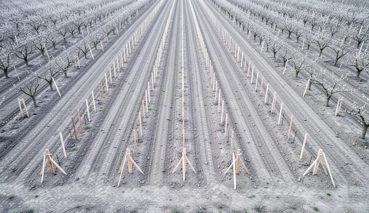
Accurate percolation data serves as the foundation for the engineering decisions required to establish a high-density, uniform tree block. Once testing is complete across the property, compile all station drop rates and soil profile notes into a baseline field map.
First, delineate zones across the block based on saturated drop rate classifications. Contiguous areas displaying rates between 30 and 60 mm/hr can be marked for standard row layout and native-grade planting. Zones yielding rates between 12 and 24 mm/hr should be slated for continuous raised planting berms (measuring 30 to 45 centimeters in height and 1.2 meters in width) to elevate root crowns above the saturation zone, coupled with the selection of rootstocks verified for moisture tolerance.
Second, for sectors displaying steady-state rates below 8 mm/hr, collect deep core samples down to 1.5 meters to check for restrictive bedrock, compacted hardpans, or persistent ground water. If these low readings stem from shallow, localized hardpans over well-draining substrata, schedule heavy subsoil ripping during late summer when the profile is dry enough to shatter. If the readings stem from heavy, uniform clay strata, engage an agricultural drainage contractor to develop an engineered drainage map and submit necessary outlet discharge permits before ordering nursery stock.