 Verdant stock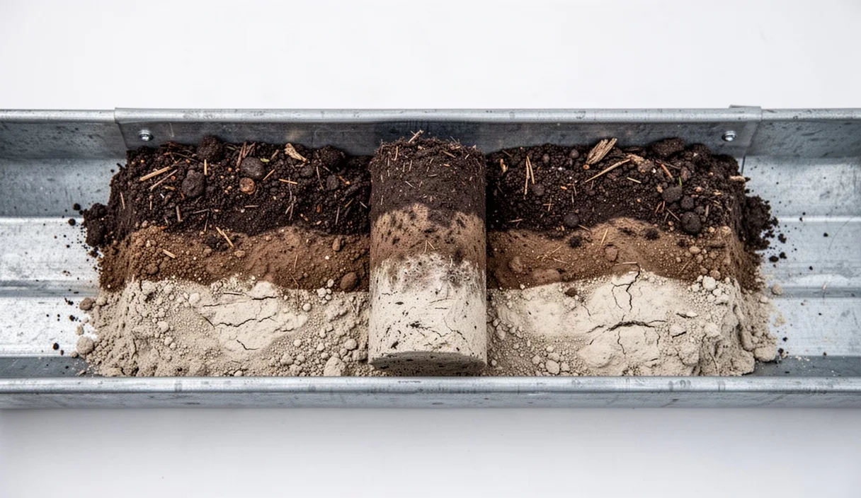

Acreage landscaping projects present spatial challenges that smaller residential sites avoid. Large properties often span multiple geological formations, drainage basins, and historic land-use zones within a single parcel. A standard topsoil grab sample sent to an analytical laboratory provides information on base chemical fertility, but it fails to document the physical stratification beneath the surface. Without an accurate vertical assessment of the soil profile, long-term investments in specimen trees, windbreaks, earthworks, and broad-scale turf can fail due to unforeseen hardpans, subsurface saturation, or abrupt textural changes.
Soil profile assessment evaluates the soil in situ down to the primary rooting depth, usually between 90 and 150 centimeters below the surface. This diagnostic process maps the thickness, structure, color, and texture of distinct soil horizons before grading, excavation, or planting schedules are finalized. Conducting this assessment early provides structural benchmarks that determine where extensive earth movement is practical, where native species will thrive without continuous intervention, and where structural drainage systems must be installed to prevent anaerobic root rot.
Collecting Undisturbed Core Samples Across Field Grids
Accurate acreage assessment relies on undisturbed soil cores that preserve the natural soil architecture, bulk density, and vertical stratification. Disturbed samples from standard screw augers destroy structural aggregates and smear moisture boundaries, obscuring critical morphological transitions. To obtain viable cores, use a slide-hammer core sampler or an open-faced gouge auger fitted with a hardened steel cutting tip and a clear butyrate plastic liner. A liner internal diameter of 50 millimeters is standard; narrower tubes cause excessive core compression during entry, which distorts horizon depth measurements.
Before entering the field, divide the parcel into distinct sampling zones using aerial imagery, topographic contour maps, and historical land-use records. Uniform fields with gentle slopes below 3 percent can be evaluated on a regular grid of 60 meters by 60 meters. Where slopes exceed 5 percent, or where landforms shift from crest to valley bottom, adopt a toposequence approach. Place sample stations along the catena: shoulder, backslope, footslope, and toeslope. This stratification accounts for how surface water movement and gravity redistribute fine sediments over time.
Execute the core extraction through the following systematic procedure:
- Clear the soil surface of loose plant residue and organic litter without stripping the underlying mineral soil.
- Align the coring cylinder perpendicular to the ground plane, verifying vertical alignment with a small spirit level.
- Drive the cylinder smoothly into the ground using the slide hammer until the target depth of 120 centimeters is reached, avoiding lateral rocking that creates air voids along the tube wall.
- Rotate the hammer assembly 180 degrees to sheer the core base from the surrounding subsoil mass.
- Extract the sampler using a steady vertical pull, or employ a mechanical jack if the suction within heavy clay soils prevents manual removal.
- Cap both ends of the core immediately, label the exterior with the station coordinates and surface elevation, and store the cylinder horizontally in a padded carrying trough away from direct sunlight.
Identifying the Topsoil Horizon and Subsoil Transition
A vertical soil profile comprises master horizons designated by capital letters: O (organic layer), A (mineral topsoil), E (eluviated or leached layer), B (subsoil accumulation), and C (unconsolidated parent material). In acreage landscaping, the critical boundary lies between the A and B horizons. The A horizon contains the highest concentration of organic carbon, active biological populations, and non-capillary macropores. The underlying B horizon functions as the structural reservoir for water and secondary minerals, often displaying higher bulk densities and elevated concentrations of illuviated clay or iron oxides.
Identify horizons by examining clean, freshly split core surfaces rather than smeared exterior walls. Horizon boundaries are characterized by their distinctness, which is measured across the vertical thickness of the transition zone:
- Abrupt boundary: The transition between layers is less than 2 centimeters thick. This condition often signals an anthropogenic disturbance, an erosional contact, or a sharp textural contrast such as sand over dense clay.
- Clear boundary: The transition spans 2 to 5 centimeters. This is common in mature, undisturbed agricultural and forest soils.
- Gradual boundary: The transition spans 5 to 15 centimeters, indicating consistent biological mixing by earthworms and plant roots over centuries.
- Diffuse boundary: The transition exceeds 15 centimeters, requiring careful tactile texturing to determine where the topsoil influence yields to subsoil characteristics.
Note transitional horizons where characteristics blend. An AB horizon designates a layer dominated by mineral topsoil properties but displaying minor clay accumulation or subsoil structure. A BA horizon denotes a subsoil layer that retains substantial organic staining from above. If an ash-colored, pale zone appears between the dark topsoil and the denser subsoil, this indicates an E horizon. An E horizon shows that lateral subsurface water movement has leached away organic pigments, silicate clays, and iron compounds, leaving behind a pale layer of pure quartz sand and silt that exhibits minimal nutrient retention capacity.
Recognizing Gleying and Mottling as Drainage Indicators
Soil color serves as the primary visual indicator of historic moisture dynamics. While bright brown, red, and yellowish-tan colors indicate aerobic conditions with abundant oxygen, dull gray and mottled colors reveal prolonged anaerobic saturation. Under waterlogged conditions, microbial activity consumes available dissolved oxygen within 48 to 72 hours. Facultative and anaerobic bacteria then use oxidized ferric iron (Fe3+) as an electron acceptor, reducing it to soluble ferrous iron (Fe2+). This reduced iron is mobilized and leached out of the soil matrix, leaving behind bare mineral particles that exhibit a gray, bluish, or olive hue known as gleying.
Gleyed horizons, described formally as reductimorphic matrices, are classified using the Munsell Soil Color system. Any mineral soil matrix displaying a chroma of 2 or less, combined with a value of 4 or higher on hues 10YR, 2.5Y, 5Y, or the specialized Gley pages, points to sustained saturation. If these neutral gray colors occur directly below the A horizon, the location experiences a seasonal high water table that will limit the root development of most non-riparian woody ornamental plants.
Where the water table fluctuates seasonally, alternating between saturated and aerated states, the soil develops mottles, known technically as redoximorphic concentrations. When the water table falls, oxygen re-enters macropores and root channels. Soluble ferrous iron oxidizes rapidly, precipitating out as insoluble ferric oxide minerals. These appear as distinct red, orange, or yellow-brown spots, irregular splotches, or firm nodules set against a paler matrix.
| Redox Feature | Visual Morphology | Hydrologic Condition | Landscape Consequence |
|---|---|---|---|
| Continuous Gleying | Uniform matrix color: gray, slate, or greenish-gray (chroma 1 or 2) | Permanent saturation within 20 cm of the observed layer; strictly anaerobic. | Roots of typical upland trees suffocate. Siting requires specialized wetland species or deep relief ditching. |
| Prominent Mottling | Matrix interspersed with bright orange or reddish-brown concentrations (7.5YR 5/8) | Episodic saturation; water table rises during rainy cycles and drops during dry periods. | Root pruning occurs during wet seasons. Excavated pits may collect perched water during spring. |
| Pore Linings | Rust-colored tubes lining former root channels and ped faces | Brief waterlogging events where oxygen diffusion follows biological channels. | Subsoil structure allows slow drainage, but internal percolation is impeded below the lining depth. |
| Manganese Nodules | Small, hard, irregular black or purplish-black concretions | Fluctuating boundary zones with very slow oxidation rates. | Indicates boundary layers prone to periodic stagnation, often directly above dense claypans. |
Field Texturing by Ribbon and Sieve Methods
The physical behavior of each horizon depends on its particle size distribution, which divides mineral components into sand (2.00 to 0.05 mm), silt (0.05 to 0.002 mm), and clay (smaller than 0.002 mm). Textural classification dictates water-holding capacity, nutrient cation exchange capacity, aeration, and compaction risk. Determine the texture in the field by coupling manual ribbon manipulation with field-expedient dry sieving.
Execute the ribbon method directly on representative samples taken from the center of each identified horizon. Remove all rock fragments and plant roots larger than 2 millimeters. Place approximately 25 grams of soil in the palm of your hand and moisten it incrementally with clean water, kneading it until it reaches the consistency of workable putty, resembling modeling clay. If the soil becomes wet and soupy, add dry field soil from the same horizon to correct the moisture level.
Form the conditioned sample into a uniform ball roughly 3 centimeters in diameter. Roll the ball between your palms to form a cylinder roughly 15 millimeters thick. Place the cylinder over your forefinger and push it outward with your thumb, squeezing it into a flat ribbon of uniform 3-millimeter thickness. Allow the ribbon to extend off the edge of the forefinger under its own weight until it breaks. Measure the broken ribbon segment with a pocket rule:
- Ribbon less than 2.5 centimeters: Coarse texture. If the wet sample feels gritty with no cohesion, it is sand or loamy sand. If it feels smooth and floury with minimal cohesion, it is silt loam. If it exhibits moderate grit and cohesion, classify it as loam.
- Ribbon between 2.5 and 5.0 centimeters: Medium texture. Gritty resistance indicates sandy clay loam; a smooth, talc-like feel denotes silty clay loam; an intermediate, balanced feel points to a standard clay loam.
- Ribbon longer than 5.0 centimeters: Fine texture with high clay content. Gritty feel indicates sandy clay; smooth, satiny feel indicates silty clay; an intensely stiff, sticky, and shiny surface when rubbed against the skin marks a pure clay.
To quantify the gravel and stone fraction that the ribbon test excludes, pass a 500-gram dry bulk sample through a standard stainless steel No. 10 mesh field sieve (2.0-millimeter aperture). Weigh the retained coarse fragments on a field scale and calculate their mass percentage against the original bulk weight. If coarse fragments comprise between 15 and 35 percent of the total volume, prefix the texture name with gravelly (for example, gravelly loam). If coarse fragments comprise 35 to 60 percent, apply the modifier very gravelly. High gravel fractions reduce total water-holding capacity proportionally, requiring larger irrigation zones or lower canopy densities.
Species Allocation Based on Horizon Thickness
A successful acreage landscape plan aligns planting zones with subsurface physical realities rather than aesthetic preferences alone. Horizon thickness and depth to restrictive layers determine available water capacity and the physical rooting space available to mature root architectures. For woody plants, the root plate requires adequate structural anchorage, which cannot develop if a dense fragipan, bedrock, or continuous gleying lies close to the surface.
Measure the effective rooting depth, which is the total depth from the surface down to the first root-limiting layer. Root-limiting layers include unweathered bedrock, high-density basal tills with bulk densities exceeding 1.65 grams per cubic centimeter, or sustained anaerobic gley matrices. Group planting areas into depth classes and allocate functional vegetation groups accordingly.
| A Horizon Depth | Effective Rooting Depth | Subsoil Characteristics | Optimal Species Strategy |
|---|---|---|---|
| Less than 10 cm | Under 40 cm | Dense, non-rippable clay or shallow lithic contact | Shallow-rooted prairie grasses, sedges, low-growing native scrub. Avoid large canopy shade trees that risk windthrow. |
| 10 to 20 cm | 40 to 75 cm | Mottled clay loam with perched water table at 50 cm | Facultative wetland species, taprooted shrubs, medium trees tolerant of seasonal saturation (e.g., Acer rubrum, Betula nigra). |
| 20 to 35 cm | 75 to 110 cm | Friable blocky structure, well-aerated B horizon | General canopy trees, extensive turfgrass lawns, structural windbreaks (e.g., Quercus macrocarpa, Pinus strobus). |
| Greater than 35 cm | Over 110 cm | Deep, well-drained alluvial or loess-derived loam | High-demand specimen plantings, intensive orchard blocks, deep-rooted taproot species (e.g., Carya ovata, Juglans nigra). |
Where topsoil depth measures under 12 centimeters, surface excavation for roads or patios must not strip the remaining A horizon from adjacent green space. Stripping thin topsoils exposes structurally weak subsoils that crust under rainfall, preventing seedling establishment. When planting taproot species in soils with B horizon transitions that show abrupt boundaries, pre-drill vertical root-paths through the boundary layer using a hydraulic tree auger, backfilling the shaft with an equal mix of native subsoil and coarse sand to facilitate downward anchor root elongation.
Common Mistakes
- Compositing multi-depth soil samples: Blending soil gathered from the top 10 centimeters with soil extracted from 45 centimeters into a single bucket destroys profile resolution. The resulting laboratory data yields an average value that represents none of the actual horizons in the field.
- Conducting drainage surveys exclusively in dry periods: Saturated horizons dry out during late summer droughts. Relying on soil moisture rather than redoximorphic features (mottles and low chroma) leads to planting upland species in zones that become saturated during winter and spring.
- Over-tilling structural subsoils: Attempting to improve low-permeability B horizons by deep rototilling breaks down natural subangular blocky peds into single-grain dust. Upon the first saturating rain event, this pulverized material collapses into a massive, structureless state with lower hydraulic conductivity than the original undisturbed subsoil.
- Misidentifying parent material color as dynamic mottling: Some geologic parent materials, such as weathered red shales or glauconitic sands, contain native red or green pigments unrelated to modern moisture regimes. Always compare subsoil colors against unaltered regional geologic formations to verify if color variations reflect real redoximorphic processes.
Practical Next Steps
To implement a structured assessment on an acreage site, begin by assembling physical baseline records. Obtain the pertinent regional soil survey reports, typically accessible through national soil conservation databases, and overlay these preliminary soil maps onto high-resolution property topography. Mark known drainage paths, low-lying collection swales, and planned infrastructure alignments directly onto this base document.
Fabricate or procure the necessary sampling gear: an open-faced gouge auger or slide-hammer core sampler, a Munsell Soil Color book, a standard 2-millimeter hand sieve, a 10 percent hydrochloric acid dropper bottle for carbonate detection, and a pocket metric rule. Lay out the field stations, numbering each point systematically. Log the field observations on site-specific profile sheets, recording horizon depths, boundaries, textures, colors, and the precise elevation of any redoximorphic features.
When the assessment reveals complex structural challenges, such as deep fragipans, expansive montmorillonitic clays, or contaminated fill layers, do not rely solely on field-expedient texturing. Collect representative physical samples from the target horizons and submit them to an accredited agricultural or geotechnical soil mechanics laboratory for hydrometer particle-size analysis and bulk density testing. For sites involving structural slopes, earth-dam construction, or broad-scale stormwater infiltration basins, retain a licensed professional soil scientist or geotechnical engineer to review the final profile logs before deploying earth-moving machinery.